


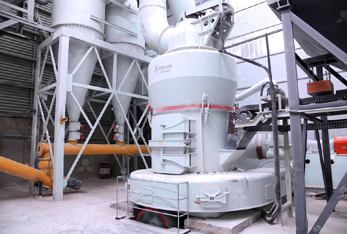
MTW European Type Trapezium Mill
Input size:30-50mm
Capacity: 3-50t/h
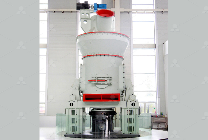
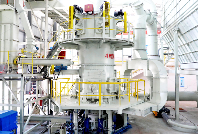
LM Vertical Roller Mill
Input size:38-65mm
Capacity: 13-70t/h
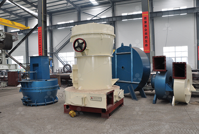
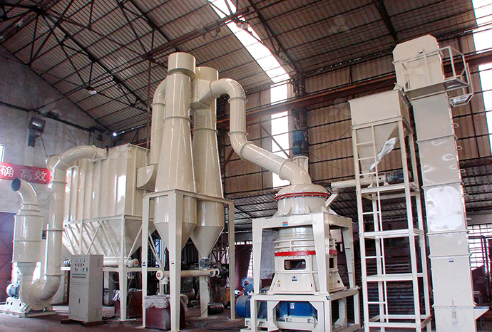
Raymond Mill
Input size:20-30mm
Capacity: 0.8-9.5t/h
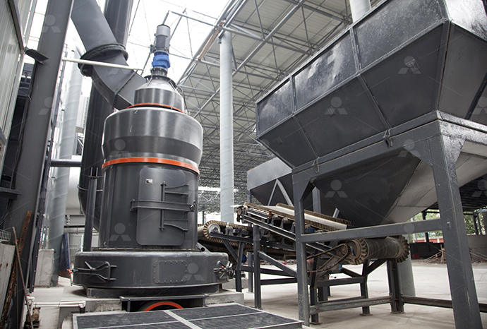
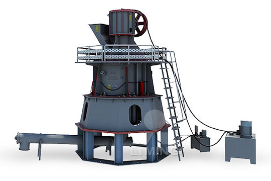
Sand powder vertical mill
Input size:30-55mm
Capacity: 30-900t/h
LUM series superfine vertical roller grinding mill
Input size:10-20mm
Capacity: 5-18t/h
MW Micro Powder Mill
Input size:≤20mm
Capacity: 0.5-12t/h

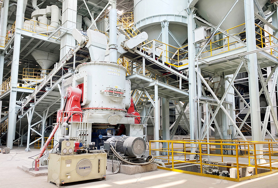
LM Vertical Slag Mill
Input size:38-65mm
Capacity: 7-100t/h

LM Vertical Coal Mill
Input size:≤50mm
Capacity: 5-100t/h
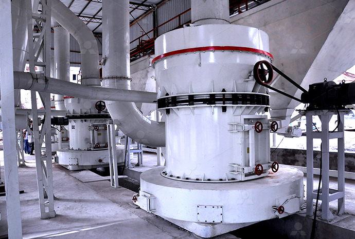
TGM Trapezium Mill
Input size:25-40mm
Capacity: 3-36t/h
MB5X Pendulum Roller Grinding Mill
Input size:25-55mm
Capacity: 4-100t/h
Straight-Through Centrifugal Mill
Input size:30-40mm
Capacity: 15-45t/h
Engineering Drawing Crusher Three View

Crusher Machine Parts Drawing GrabCAD
2022年5月4日 Crusher machine's parts on 2D drawing paper with third point of view using Autodesk Inventor, also assemblied crusher machineThe document discusses how to draw the third view of an object when given two existing views It explains that two views are typically sufficient to describe a 3D object as either a side view and elevation or a plan and elevationEngineering Drawing: Missing View PDF Scribd2023年5月28日 The GrabCAD Library offers millions of free CAD designs, CAD files, and 3D models Join the GrabCAD Community today to gain access and download!Drawings of various crushers and screening equipment GrabCADThere are three main steps in designing a good crushing plant: process design, equipment selection, and layout The first two are dictated by production requirements and design Crushing Plant Design and Layout Considerations 911 Metallurgist
.jpg)
3D modeling isometric view of a crusher ResearchGate
3D modeling isometric view of a crusher Organic waste can be used for something of value, such as compost, feed pellet, biomass pellet, and briquette Before becoming such things, it takes aDownload scientific diagram Isometric projection of the hammer mill working drawing from publication: Design and Performance Evaluation of a Stone Crusher Crushers are essential machinesIsometric projection of the hammer mill working drawingCrushing is the process of reducing the size of solid particles into definite smaller sizes Jaw crushers are major size reduction machines used in mechanical, metallurgical and allied “Computer Aided Design of Jaw crusher” 911 MetallurgistAnother example of a threeview drawing: Figure 316 shows a 3view representation of the support bracket from Figure 315 Note that on standard drawings the specific views will not 3 INTERPRETATION OF DRAWINGS Department of Mechanical
.jpg)
Free CAD Designs, Files 3D Models The GrabCAD Community
The GrabCAD Library offers millions of free CAD designs, CAD files, and 3D models Join the GrabCAD Community today to gain access and download!The purpose of this project is to evaluate the kinematic and static force analysis of a single toggle jaw crusher that employs the simple technology of a four bar mechanism, and design a small COLLEGE OF ARCHITECTURE AND ENGINEERING SCHOOL OF ENGINEERING DRAWING STANDARDS MANUAL Mechanical Engineering Branch Goddard Space Flight Center Greenbelt, Maryland August 1994 N A T I O N A L I A E R O N A U T I C S A N D S P A C E A D M I N S T R A T I O U S A National Aeronautics and Space Administration Goddard Space Flight Center Greenbelt, Maryland 20771ENGINEERING DRAWING STANDARDS MANUAL NASAIts sources can often be rooted in clearances present in mechanical joints due to manufacturing tolerances or wear [1][2][3] In some cases, impact is bound with the main function of machines, as A schematic drawing of the analysed hammer crusher
Engineering drawing Wikipedia
An engineering drawing is a type of technical drawing that is used to convey By applying what we now call mechanical drawing techniques to depict threedimensional machinery on a twodimensional plane more efficient Understandingthetypesofviewsinengineeringdrawing Technical Blogs, SkillLync offers industry relevant advanced engineering courses for engineering students by partnering with industry experts Menu Executive Programs Workshops Projects Blogs Careers Student Reviews For Business More Academic Training Informative ArticlesUnderstandingthetypesofviewsinengineeringdrawing 2024年8月27日 The following are the different types of views often used in engineering drawing: Isometric view (dimetric and trimetric view) Orthographic view (front, side, top, bottom and back views) Section view; Cutout view; Detailed view; Auxiliary view; Exploded view Isometric view; Isometric drawings show parts as threedimensional The Understanding The Types Of Views in Engineering Drawing Skill This crosssectional view (section AA, figure 17), one that is orthogonal to the viewing direction, shows the relationships of lengths and diameters better These drawings are easier to make than isometric drawings Seasoned engineers can interpret orthogonal drawings without needing an isometric drawing, but this takes a bit of practiceEngineering Drawings University of Cambridge
Reconstruction of quadric surface solids from threeview engineering
1998年6月1日 A mechanical part reconstructed from threeview drawings with planar, cylindrical, conical and spherical faces Download: Download fullsize image; Fig 10 A mechanical part reconstructed from threeview drawings with straight lines, circular and elliptical arcs Download: Download fullsize image; Fig 11Students use a tensioncompression machine (or an alternative bonebreaking setup) to see how different bones fracture differently and with different amounts of force, depending on their body locations Teams determine bone mass and volume, calculate bone density, and predict fracture force Then they each test a small animal bone (chicken, turkey, cat) to failure, examining the Bone Crusher Activity TeachEngineeringThis set of Engineering Drawing Multiple Choice Questions Answers (MCQs) focuses on “MultiView Projections” 1 In engineering drawings, the threeview multiview drawing is standard What are the collections of threeview drawings? a) The top, front, and the leftside views b) The front, bottom and the rightside viewsMultiView Projections Questions and Answers SanfoundryThe two main types of views (or “projections”) used in drawings are: pictorial; orthographic; Pictorial views Pictorial views show a 3D view of how something should look when completed There are three types of pictorial views: perspective; isometric; oblique; Perspective view A perspective view presents a building or an object just as 41: Types of views used in drawings Workforce LibreTexts
.jpg)
Crushing Plant Design and Layout Considerations 911 Metallurgist
• Electronic control of crusher discharge opening and feed rate With adjustment of a crusher’s discharge opening, as the production continues through an online coarse size analysis of the crushed product (digital image analyses) Dance, A 2001) • More attention is being paid to the impact on crushing circuit design caused by variationsDifferent Types of Engineering Drawing Views There are various types of views in an engineering drawing Each of them serves different purposes Note that you should only include a view that contributes to a design’s overall Engineering Drawing: 8 Tips to Improve Engineering 2019年5月31日 Based on the mechanism used crushers are basically of three types; namely, Cone crusher, Jaw crusher, and Impact Crusher The main objective is to design impact stone crusher(PDF) Design of Impact stone crusher machineHere is an example of an engineering drawing (an isometric view of the same object is shown above) The different line types are colored for clarity Black = object line and hatching Red = hidden line Blue = center line of piece or opening Magenta = phantom line or cutting plane lineHistory of engineering drawing Engineering drawing of a
COLLEGE OF ARCHITECTURE AND ENGINEERING SCHOOL OF ENGINEERING
COLLEGE OF ARCHITECTURE AND ENGINEERING SCHOOL OF ENGINEERING DEPARTMENT OF MECHANICAL AND MANUFACTURING ENGINEERING MECHANICAL DESIGNOF A SMALL SCALE MECHANIZED STONE CRUSHER A final year project for the partial fulfillment for the award of bachelor’s degree in Mechanical and Manufacturing 2019年8月17日 PDF This book includes practice problems for Engineering Drawing course Find, Translate them into threeview orthographic drawings Use first angle projection for odd PRACTICE PROBLEMS FOR ENGINEERING DRAWING IFeatures of Engineering Drawings Engineering Drawings convey the following critical information: • Geometry: The shape of the object represented as views, ie how the object will look when you view it from various angles such as the front, top and side • Dimensions: The size of the object • Tolerances: The allowable variations for each dimension • Material: What the item is made of Engineering Drawings Overview Research Examples Perlegoasme y1424, “drawings types and applications of engineering drawings”, was adopted on 14 February 2000 for use by the Department of Defense (DoD) Proposed changes by DoD activities must beTypes and Applications of Engineering Drawings ASME
.jpg)
Chapter 4 Orthographic Projection and Multiview Constructions
Multiview drawings usually require several orthographic projections to define the shape of a threedimensional object Each orthographic view is a twodimensional drawing showing only two of the three dimensions of the threedimensional object Consequently, no individual view contains sufficient information to completely define the shape of the2020年11月3日 Students are introduced to detail drawings and the importance of clearly documenting and communicating their designs They are introduced to the American National Standards Institute (ANSI) Y145 standard, which controls how engineers communicate and archive design information They are introduced to standard paper sizes and drawing view Lesson Detail Drawings: Communicating with EngineersTechnical drawings are the language engineers and architects use to communicate their ideas and designs to journeymen ThreeView, Plan View and Elevation View Drawings Specification for Graphical symbols for ThreeView, Plan View and Elevation View This document is a final year project report submitted by Henok Girma to the Mechanical Engineering Department of Mekelle University in partial fulfillment of a Bachelor of Science degree The project involves designing a feeder system Design of Feeder System For Crusher Plant PDF
Multiview Drawings – EngineeringTechnology
This consistency ensures that anyone reading the drawing can accurately understand the spatial relationships and dimensions of the object Different projection systems, such as firstangle and thirdangle projection, are employed in multiview drawings, influencing how the views are arranged on the drawing sheetThreeView, Plan View and Elevation View Drawings Engineering ThreeView, Plan View and Elevation View Drawings Engineering MRCET(UGC AUTONOMOUS) Dept of Mechanical Engineering Page 3 ENGINEERING DRAWING PRACTICE MANUAL I BTech Figure 14 Title Block: The title block should lie within the drawing space at the bottom right hand com er of the sheet The title block can have a maximum length of 170 mm and width of 65mm providing the f ollowingENGINEERING DRAWING PRACTICE MANUALEngineering Drawing is one of the basic courses to study for all engineering disciplines The primary problem faced in learning and teaching of engineering drawing is the limited availability of text books that focus on the basic rules and specifications in relation to the drawing methods practiced in Bangladesh(PDF) Engineering Drawing for Beginners Academia
.jpg)
Engineering Drawings 05 understanding drawing views
2022年11月2日 This Video Series is designed for manufacturing or supply chain professionals who want to better understand engineering drawings So often, engineering and dWorking drawings represent just one category within a diverse spectrum of engineering drawings, each tailored to serve specific functions in the design, manufacturing, and construction processes According to standards like ASME Y1424, engineering drawings encompass a variety of types, each providing different levels of detail and perspectives on a component, product, or systemWorking Drawings – EngineeringTechnologyContribute to lbsid/en development by creating an account on GitHuben/168/engineering drawing of rock crushermd at main2019年8月17日 Draw the perspective view of a cube of 25 mm edge, resting on ground with one of its faces It has one o f its vertical edges in the picture p lane and all its vertical faces are equallyPRACTICE PROBLEMS FOR ENGINEERING DRAWING II

ENGINEERING DRAWING STANDARDS MANUAL NASA
ENGINEERING DRAWING STANDARDS MANUAL Mechanical Engineering Branch Goddard Space Flight Center Greenbelt, Maryland August 1994 N A T I O N A L I A E R O N A U T I C S A N D S P A C E A D M I N S T R A T I O U S A National Aeronautics and Space Administration Goddard Space Flight Center Greenbelt, Maryland 20771Its sources can often be rooted in clearances present in mechanical joints due to manufacturing tolerances or wear [1][2][3] In some cases, impact is bound with the main function of machines, as A schematic drawing of the analysed hammer crusherAn engineering drawing is a type of technical drawing that is used to convey By applying what we now call mechanical drawing techniques to depict threedimensional machinery on a twodimensional plane more efficient Engineering drawing WikipediaUnderstandingthetypesofviewsinengineeringdrawing Technical Blogs, SkillLync offers industry relevant advanced engineering courses for engineering students by partnering with industry experts Menu Executive Programs Workshops Projects Blogs Careers Student Reviews For Business More Academic Training Informative ArticlesUnderstandingthetypesofviewsinengineeringdrawing

Understanding The Types Of Views in Engineering Drawing Skill
2024年8月27日 The following are the different types of views often used in engineering drawing: Isometric view (dimetric and trimetric view) Orthographic view (front, side, top, bottom and back views) Section view; Cutout view; Detailed view; Auxiliary view; Exploded view Isometric view; Isometric drawings show parts as threedimensional The This crosssectional view (section AA, figure 17), one that is orthogonal to the viewing direction, shows the relationships of lengths and diameters better These drawings are easier to make than isometric drawings Seasoned engineers can interpret orthogonal drawings without needing an isometric drawing, but this takes a bit of practiceEngineering Drawings University of Cambridge1998年6月1日 A mechanical part reconstructed from threeview drawings with planar, cylindrical, conical and spherical faces Download: Download fullsize image; Fig 10 A mechanical part reconstructed from threeview drawings with straight lines, circular and elliptical arcs Download: Download fullsize image; Fig 11Reconstruction of quadric surface solids from threeview engineering Students use a tensioncompression machine (or an alternative bonebreaking setup) to see how different bones fracture differently and with different amounts of force, depending on their body locations Teams determine bone mass and volume, calculate bone density, and predict fracture force Then they each test a small animal bone (chicken, turkey, cat) to failure, examining the Bone Crusher Activity TeachEngineering
.jpg)
MultiView Projections Questions and Answers Sanfoundry
This set of Engineering Drawing Multiple Choice Questions Answers (MCQs) focuses on “MultiView Projections” 1 In engineering drawings, the threeview multiview drawing is standard What are the collections of threeview drawings? a) The top, front, and the leftside views b) The front, bottom and the rightside viewsThe two main types of views (or “projections”) used in drawings are: pictorial; orthographic; Pictorial views Pictorial views show a 3D view of how something should look when completed There are three types of pictorial views: perspective; isometric; oblique; Perspective view A perspective view presents a building or an object just as 41: Types of views used in drawings Workforce LibreTexts