


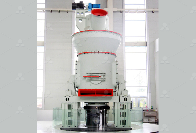
MTW European Type Trapezium Mill
Input size:30-50mm
Capacity: 3-50t/h
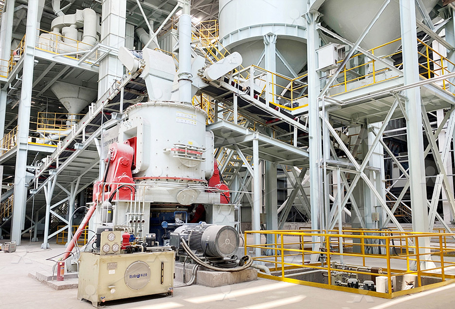
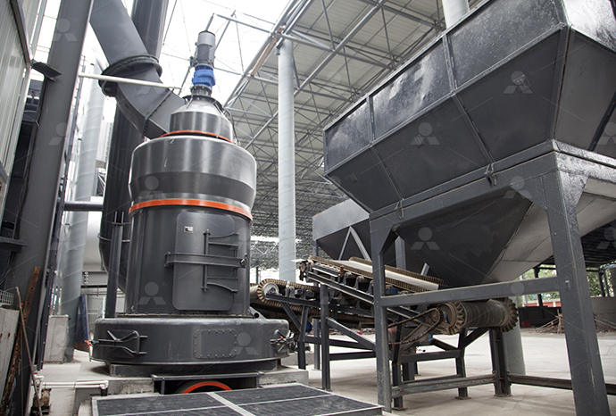
LM Vertical Roller Mill
Input size:38-65mm
Capacity: 13-70t/h
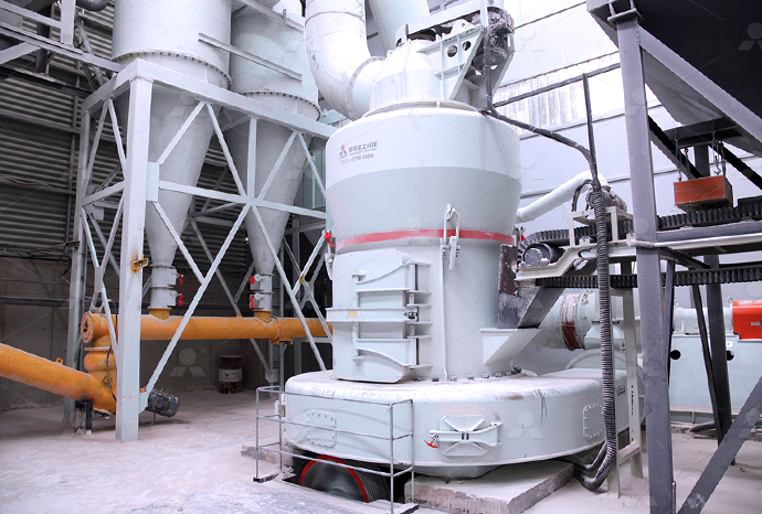
Raymond Mill
Input size:20-30mm
Capacity: 0.8-9.5t/h
Sand powder vertical mill
Input size:30-55mm
Capacity: 30-900t/h
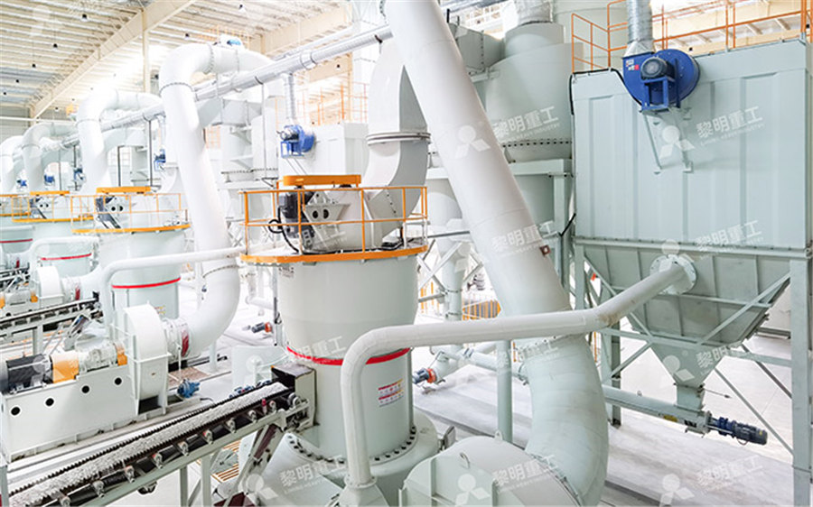
LUM series superfine vertical roller grinding mill
Input size:10-20mm
Capacity: 5-18t/h
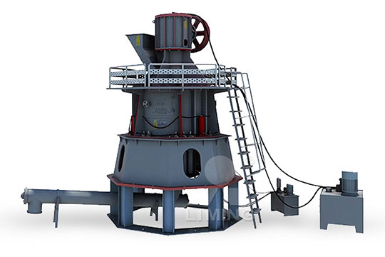
MW Micro Powder Mill
Input size:≤20mm
Capacity: 0.5-12t/h

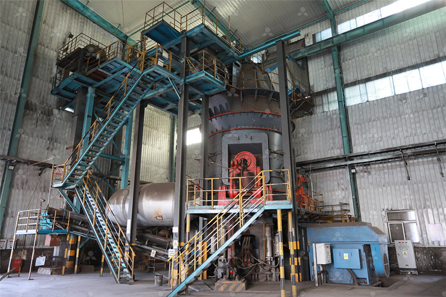
LM Vertical Slag Mill
Input size:38-65mm
Capacity: 7-100t/h
LM Vertical Coal Mill
Input size:≤50mm
Capacity: 5-100t/h
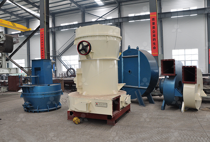
TGM Trapezium Mill
Input size:25-40mm
Capacity: 3-36t/h
MB5X Pendulum Roller Grinding Mill
Input size:25-55mm
Capacity: 4-100t/h
Straight-Through Centrifugal Mill
Input size:30-40mm
Capacity: 15-45t/h
552 stage reducer shaft diameter
A New Design of a TwoStage Cycloidal Speed Reducer
stage cycloidal speed reducers A singlestage reducer engages two identical cycloid discs in order to balance dynamical loads and to obtain uniform load distribution Consequently, the It is 2 stage reduction gearbox along with reversal transmission system induced with efficient output and comparatively lesser weight All this achieved by studying the gear ratio and Design and Analysis of Two Stage Reduction Gearbox IRJET2008年11月7日 In this paper an optimal design of twostage speed reducer is presented The novelty of this article consists in the complex and complete approach of the optimal design of gearings The chosen(PDF) Optimal design of twostage speed reducerAbstract: In this paper an optimal design of twostage speed reducer is presented The novelty of this article consists in the complex and complete approach of the optimal design of gearings Optimal design of twostage speed reducer WSEAS
.jpg)
Optimal design of twostage speed reducer using twophase
Abstract—In this paper an optimal design of twostage speed reducer is presented The novelty of this work consists in the complex and complete approach of the optimal design of gearings 2014年2月1日 The full description of a twostage speed reducer generally requires a large number of design variables (typically, well over ten), resulting a very large and heavily Optimal mass minimization design of a twostage coaxial helical In this paper a Genetic Algorithm (GA) was used for obtaining optimal models for partial gear ratios in order to achieve a 3 stage helical speed reducer with minimum mass or length The Optimal design of twostage speed reducer AcademiaNew twostage cycloid drive concept efficiency is done for 8 standard power values from 025kW to 15kW, with various input RPM and various transmission ratios In order to evaluate the Vol 42, No 2 (2020) 337343, DOI: 1024874/ti880052006
Analysis of TwoStage Cycloid Speed Reducers Dimensions and
The classical conception of a twostage cycloid speed reducer consists of two coaxial singlestage cycloid speed reducers The output shaft of the first stage is also the input shaft of the second 2014年2月1日 To obtain minimum volume of spur gear drive is objective of the problem The considered design variables are: Module, number of teeth, base width of the gears and, shaft diameter and powerOptimal mass minimization design of a twostage Figure 1: Twostage speed reducer Determine the rpm of shafts b and c, the pitch diameters of the pinion and gear, and the circular pitch Determine the torque carried by each of the shafts ab and c Determine the radial loads SOLVED: Question 4 Fig 2 shows a twostage gear Figure shows a twostage gear reducer except for the geartooth forces Determine the rpm of shafts b and c, the pitch diameters of the pinion and gear, and the circular pitch Determine the torque carried by each of the shafts a, b, Solved Figure shows a twostage gear reducer
Determining Optimal Gear Ratios of a Twostage Helical Reducer
reducers [1, 2, 3 and 4], threestage reducers [4, 5, 6, and 8], and fourstage reducers [4, 8, 9 and 10] Also, the gear ratios have been found using different methods including For a twostage reducer, the diameters d w11, d w21 and d w22 can be determined as the following equations2011年8月1日 A traditional twostage cycloidal speed reducer is obtained by the Find, read and cite all the research you need on ResearchGate Home Physiological ProcessesA New Design of a TwoStage Cycloidal Speed ReducerReplacing drive shafts can be costly, and even unnecessary if the only issue is having an incorrect shaft size Bore reducers, also called shaft adaptors or bore adaptors, provide a solution by allowing you to increase the diameter of your shaft These clampstyle adaptors attach to the end of a shaft to enable the connection to an incompatible Bore Reducer Adaptors Custom Shaft Adaptors CouplingsFind your twostage gear reducer easily amongst the 380 products from the leading brands (Bonfiglioli, Portescap, Framo, right angle hollowshaft 2 5 kNm worm gearbox RA series Rotational speed: 1,800, 200mm diameter, Plastic, sintered metal, and processed metal, Twostage gear reducer, Twostage gearbox DirectIndustry
.jpg)
Typical twostage spur gearbox Download Scientific Diagram
A twostage spur gearbox design problem is formulated with eight design variables viz facewidth (stage 1), facewidth (stage 2), shaft diameter (stage 1), shaft diameter (stage 2), module 2019年8月18日 PDF The multistage reducer, especially the planetary gear reducer, usually serves in heavyduty machinery such as shield tunneling machine, and shaft diameter can be derivedDesign Optimization of a ThreeStage Planetary Gear Reducer 3 The ‘genotype’ of the twostage reducer The class of reducers we are considering here (see Fig 1 for an example) is highly standardised, both in terms of the design of their gearings and bearings and in terms of their layout The set of 18 design variables that define the reducer unequivocally (see Table 1) reflects this, withAutomated optimal design of a twostage helical gear reducerDAYTON Speed Reducer: 575:1, 30 955 inlb Overhung Load Capacity 660 ftlb Input Connection Type CFace Output Shaft Diameter 1 in Maximum Output Speed 30 RPM Maximum Input Speed 1,750 RPM Motor Frame Designation 56C Base to Shaft Center 488 in Gear Ratio 575:1 Gear Type Helical Gear Material Hardened and Ground Steel Number DAYTON, 575:1, 30 RPM, Speed Reducer 2Z9322Z932 Grainger
.jpg)
Solved The doublereduction, helical gear reducer
Question: The doublereduction, helical gear reducer shown in Figure P1235 transmits 50 hp SH +2 NI Output 1 1 Shaft 3 Input Shaft 1*2114 Shaft 2 All helical gears Data in problem statement FIGURE P1235 (Problem 35) ducer (1—input shaft with the eccentric (the first stage), 2—the first stage cycloid discs, 3—stationary ring gear of the first stage, 4—output disc of the first stage with output A New Design of a TwoStage Cycloidal Speed Reducer2010年9月1日 the range [− 2 5%, 2 5%] on b oth stages Constraint group 2 The Hertzian contact pr essure on the teeth of b oth stages must not exce ed a sp ecifie d valueAutomated optimal design of a twostage helical Identical pairs of gears are used (This enables input shaft a and output shaft c to be colinear, which facilitates machining of the gear box housing) Shaft b, also called the countershaft, turns freely in bearings A and B Suppose the system is to run 8 hours per day, 5 days a week, and last for 10 years Light shock load might be encounteredSolved The figure below shows a twostage gear reducer
Calculation and Optimization of the Two Stage Worm Gear Reducers
2023年2月1日 This paper discusses worm gear optimization, with a focus on speed ratio in a two stage wormgear reducer, based on the conditions of equal contact stress, oilimmersed lubrication, and minimum 2021年4月26日 Page 3 of 7 Objectives: To analyze, using an online simulator, how the speeds between the input and the output shafts vary for a system of spur gears assembled as a 2stage speed reducer, as shown below Procedures: • Access the online SliderCrank Simulator, using the following link: Gear Generator • Change the size and the connection of the gears to match EMT 1220 EXP 5 Part 2pdf New York City College ofFigure 52: 2nd Spur gear has 36 teeth and 30 mm Shaft Diameter 37 Figure 53: 3rd Spur gear has 22 teeth and 25 mm Shaft Diameter Figure 54: 4th Spur gear has 22 teeth and 25 mm Shaft Diameter 38 522 Procedure for Modelling the Shafts: 1 Select the Front Plane and right click on Sketch option 2DESIGN AND ANALYSIS OF A TWO STAGE REDUCTION GEARBOX 2023年2月9日 Ref: Juvinall Fourth Edition Ch15 45 teeth 525 15 teeth Driven machine coupled to this shaft 1 kW 1200 rpm motor coupled to this shaft 100 mm 45 teeth 25 mm Figure 4: A twostage gear reducer a) Determine the RPM of the shafts b and c, the pitch diameter of the pinion and gear, and the circular pitchSOLVED: Figure below shows a twostage gear reducer
.jpg)
Design of TwoStage Speed Reducer for Manufacturing Efficiency
2024年6月22日 Shaft Design Analysis With the design of our 2stage speed reducer we can estimate that the torque from the beginning of the 2 Gear ratio is 346 to 353 ≈ 35 Gear ratio = 35 = w 1 w 2 = n 1 n 2 = d 2 d 1 = T 2 = 91 T 1 = 26 Gear 1 will have 26 teeth and shaft diameter of 15mm Gear 2 will have 91 teeth and shaft diameter of 2018年3月1日 And the diameter of the gear is 1255 inch and it has And the tot al length of the shaft is 12 inch and the spur gear d In this paper an optimal design of twostage speed reducer is (PDF) Design and Analysis of Two Stage Reduction Gearbox for All Find your shaft gear reducer easily amongst the 534 products from the leading brands train of gears solutions and nonstandard designs Helical gear units with 2, 3 and 4 gear stages Bevel helical gear units with 2, 3 And output hole diameter can be customized as neededWe currently have 50mm~110mm bore output for models CYWF50H Shaft gear reducer, Shaft gearbox All industrial manufacturers2022年12月29日 In this study, I completed my design of a 2stage spur gear reducer drawn shaft diameter can be used Check if estimates were acceptable D\d = 50\32 = 1,5625(PDF) In this study, I completed my design of a 2stage
.jpg)
—Planetary stage design, shaft design, bearing selection design
Design of a cycloid reducer —Planetary stage design, shaft design, bearing selection design, and design of shaft related parts Vaxjö Course code: 2MT00E Bachelor degree project Li Yawei Wu Yuanzhe Supervisor: Samir Khoshaba Examiner: Izudin Dugic Question: A gear box reducer system two stage (Spur Gear VBelt), the reducer consists of three shafts, 6 bearings, coupling, pair of gears, two pulleys and motor Given data: Motor Power = 25KW Speed = 1650 rpm VBelt Center distance = 1500 mm Reduction Ratio i= 3, Tension ratio TR=2, Small pulley diameter = 100 mm Spur Gear Reduction Ratio = 2 Dg= 200 mm dp=A gear box reducer system two stage (Spur Gear Chegg1 Brief introduction of M5R series 5stage rightangle shaft bevel gear reducer Mseries gear reducer is specifically designed for heavy duty load applications, that designed to ensure the use of speed gear reducer works best TXL brand heavy Mseries provides a high level of mechanical power and heat power,with excellent performance 2M5R Series 5 Stage Right Angle Shaft Bevel Gear Reducer2021年8月9日 Machine Design 2 Mechanical Engineering How to Design and Assemble Two Stage Speed Reducer ( Gear Box ) which Consist of Helical Gear Set and Spur Gear SetTwo Stage Speed Reducer (⚙Gear Box⚙) Design and Assembly in
.jpg)
(PDF) Design principles for speed reducers ResearchGate
2002年10月1日 Individual one stage reducers have been designed for each kind of gears Shafting and Strength of shafts The rest of machine elements used in a speed reducer (lubrication, snap rings, Buy FMSISIGQJ Round Flange Planetary Gearbox Reducer 2 Stage Ratio 15:1 20:1 30:1 for 57 Frame NEMA23 Stepper Motor Input Shaft Diameter 8mm(30:1): Gearboxes, Gearheads Speed Reducers Amazon FREE DELIVERY possible on Amazon: FMSISIGQJ Round Flange Planetary Gearbox Reducer 2 Stage input shaft between the bearings, length of output shaft between bearings, diameter of shaft 1 and diameter of shaft 2 The objective function was subjected to a simply formulated (from a mechanical point of view) set of 11 constraints Mezura in [17] utilized this problem only to test one of previous version of his Simple Multimembered EvolutionOptimal design of twostage speed reducer using twophase2019年9月16日 The megawatt gearbox adopts a 2stage parallel shaft +1 planetary transmission structure Due to the relatively complicated planetary transmission structure and the difficulty in processing large internal ring gears, the cost is relatively high Even with the 2stage planetary transmission, the NW transmission is the most commonThe design and analysis of a two stage reduction gearbox
SOLVED: Question 4 Fig 2 shows a twostage gear
Figure 1: Twostage speed reducer Determine the rpm of shafts b and c, the pitch diameters of the pinion and gear, and the circular pitch Determine the torque carried by each of the shafts ab and c Determine the radial loads Figure shows a twostage gear reducer except for the geartooth forces Determine the rpm of shafts b and c, the pitch diameters of the pinion and gear, and the circular pitch Determine the torque carried by each of the shafts a, b, Solved Figure shows a twostage gear reducerreducers [1, 2, 3 and 4], threestage reducers [4, 5, 6, and 8], and fourstage reducers [4, 8, 9 and 10] Also, the gear ratios have been found using different methods including For a twostage reducer, the diameters d w11, d w21 and d w22 can be determined as the following equationsDetermining Optimal Gear Ratios of a Twostage Helical Reducer 2011年8月1日 A traditional twostage cycloidal speed reducer is obtained by the Find, read and cite all the research you need on ResearchGate Home Physiological ProcessesA New Design of a TwoStage Cycloidal Speed Reducer
.jpg)
Bore Reducer Adaptors Custom Shaft Adaptors Couplings
Replacing drive shafts can be costly, and even unnecessary if the only issue is having an incorrect shaft size Bore reducers, also called shaft adaptors or bore adaptors, provide a solution by allowing you to increase the diameter of your shaft These clampstyle adaptors attach to the end of a shaft to enable the connection to an incompatible Find your twostage gear reducer easily amongst the 380 products from the leading brands (Bonfiglioli, Portescap, Framo, right angle hollowshaft 2 5 kNm worm gearbox RA series Rotational speed: 1,800, 200mm diameter, Plastic, sintered metal, and processed metal, Twostage gear reducer, Twostage gearbox DirectIndustryA twostage spur gearbox design problem is formulated with eight design variables viz facewidth (stage 1), facewidth (stage 2), shaft diameter (stage 1), shaft diameter (stage 2), module Typical twostage spur gearbox Download Scientific Diagram2019年8月18日 PDF The multistage reducer, especially the planetary gear reducer, usually serves in heavyduty machinery such as shield tunneling machine, and shaft diameter can be derivedDesign Optimization of a ThreeStage Planetary Gear Reducer
.jpg)
Automated optimal design of a twostage helical gear reducer
3 The ‘genotype’ of the twostage reducer The class of reducers we are considering here (see Fig 1 for an example) is highly standardised, both in terms of the design of their gearings and bearings and in terms of their layout The set of 18 design variables that define the reducer unequivocally (see Table 1) reflects this, withDAYTON Speed Reducer: 575:1, 30 955 inlb Overhung Load Capacity 660 ftlb Input Connection Type CFace Output Shaft Diameter 1 in Maximum Output Speed 30 RPM Maximum Input Speed 1,750 RPM Motor Frame Designation 56C Base to Shaft Center 488 in Gear Ratio 575:1 Gear Type Helical Gear Material Hardened and Ground Steel Number DAYTON, 575:1, 30 RPM, Speed Reducer 2Z9322Z932 Grainger