


MTW European Type Trapezium Mill
Input size:30-50mm
Capacity: 3-50t/h
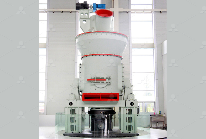
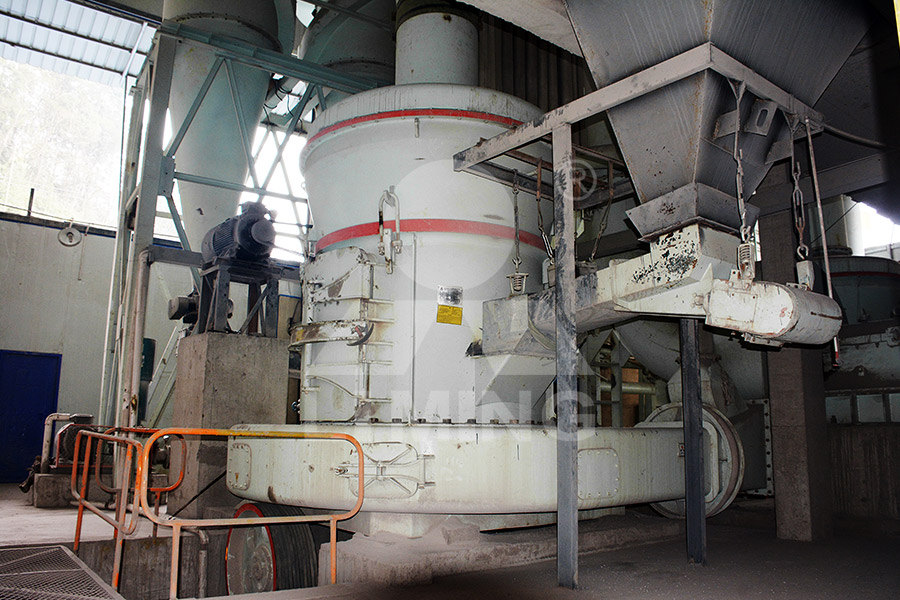
LM Vertical Roller Mill
Input size:38-65mm
Capacity: 13-70t/h
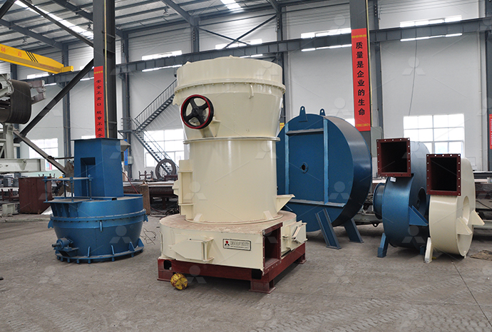
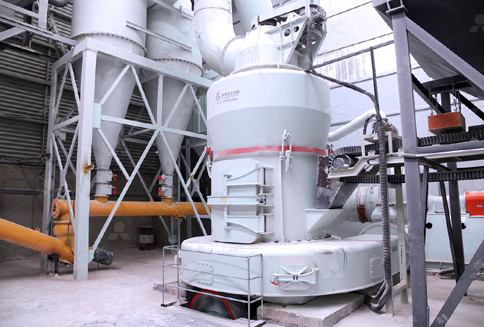
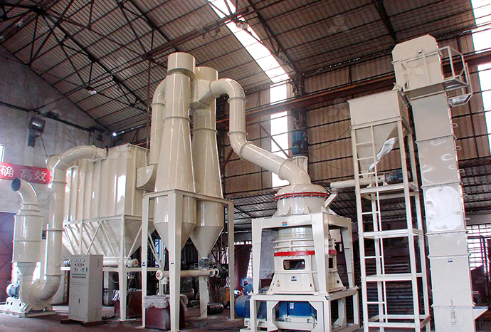
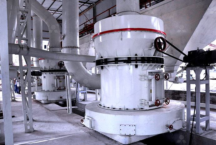
Raymond Mill
Input size:20-30mm
Capacity: 0.8-9.5t/h

Sand powder vertical mill
Input size:30-55mm
Capacity: 30-900t/h

LUM series superfine vertical roller grinding mill
Input size:10-20mm
Capacity: 5-18t/h
MW Micro Powder Mill
Input size:≤20mm
Capacity: 0.5-12t/h

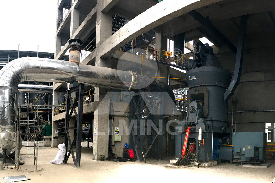
LM Vertical Slag Mill
Input size:38-65mm
Capacity: 7-100t/h

LM Vertical Coal Mill
Input size:≤50mm
Capacity: 5-100t/h
TGM Trapezium Mill
Input size:25-40mm
Capacity: 3-36t/h

MB5X Pendulum Roller Grinding Mill
Input size:25-55mm
Capacity: 4-100t/h
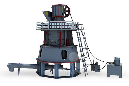
Straight-Through Centrifugal Mill
Input size:30-40mm
Capacity: 15-45t/h
Feeding controller wiring diagram
RODIX FEEDER CUBE FC40 PLUS SERIES MANUAL Pdf
View and Download Rodix FEEDER CUBE FC40 Plus Series manual online Controllers FEEDER CUBE FC40 Plus Series controller pdf manual download Also for: Feeder cube fc40240plc plus, Feeder cube fc40dcplc plus, Disclaimer The data, examples and diagrams in this manual are included solely for the concept or product description and are not to be deemed as a statement of guaranteedFeeder Protection and Control REF615 Application Manual ABBThis manual provides information on: • Mechanical/electrical installation Operation Repair/maintenance Read through all included manuals carefully, especially the sections Product Manual ABBView and Download Rodix FEEDER CUBE VF3CE wiring diagram online Variable Frequency Control OIL RESISTANT MODEL FEEDER CUBE VF3CE control unit pdf manual download Also for: Feeder cube vf series, Feeder Rodix FEEDER CUBE VF3CE Wiring Diagram ManualsLib
.jpg)
IR Drop Feeder Control (AP5986) Wiring Diagram Automated
IR Drop Feeder Control Assembly Instructions Gestation Feed System Wiring Diagram with IR Drop Feeders Figure 2 Gestation Feed System Wiring Diagram with IR Drop Feeders Control Revision C of the Coe Wintriss SFI User Manual covers all Coe Wintriss SFI versions • Adding SmartPAC 2 in addition to SmartPAC throughout the manual, including wiring diagrams Coe Wintriss ® SFIWire the Drop Feeder Control, according to the appropriate wiring diagram Unlatch and open front cover Set the desired feeding time(s) on clock by sliding out sufficient tabs to allow for Drop Feeder ControlThe hardware wiring diagram of PLC is shown in Figure 2 The operation program of intelligent feeding control system is designed into two working modes, namely, debugging mode and operationPLC I/O wiring diagram Download Scientific Diagram
.jpg)
HS689 Feed Line Control Unit Switch Assembly – 230V Single Pha
The HS689 Control Unit Switch Assembly is designed for use with a flexible auger feed system where control of an auger drive motor is required Power to the auger drive motor is done 4 ULTRAPAN Feeder Operator’s Manual Support Information (CEmark serial number) The ChoreTime ULTRAPAN® Feeding System is designed to feed poultry Using this equipment for any other purpose or in a way not within the operating recommendations specified in this manual willInstallation Operator’s Manual ChoreTimePEARL Economizer Controller Pelican Wireless Systems Installation Guide Pelican Wireless Systems, 2655 Collier Canyon Rd Livermore, CA 94551 the following charts and wiring diagrams for proper connections Pearl Economizer Controller D C R A1 A2 E C S1 S2 ACT AUX ENA COM POS EXT 010 Out 010 Out 24V Out 010 In 010 In DATA COM PWR T1 T2 PEARL Installation Guide REV04 Pelican WirelessWiring GFCI Receptacles with a Protected Outlet This gfci wiring provides protection to a duplex receptacle outlet at the end of the series By connecting the load terminals on the last gfci, the wall outlet at the end is protected and can GFCI Outlet Wiring Diagrams Doityourselfhelp

Solar System wiring connection diagram #solarsystem #wiring
2023年6月8日 Solar panel wiring connections involve the process of connecting solar panels to the rest of the solar power system This typically includes linking the indiVALCO Product Manuals provide guidance and insight on setting up, testing, and troubleshooting your new poultry or swine equipment If you have a question or require assistance, our Technical Support team is always happy to help!Product Manuals VALCO Product Installation ManualsBenefits of using a wiring diagram for installation Installing electrical components can be a complex process, especially when it comes to wiring One way to simplify this process is by using a wiring diagram A wiring diagram is a visual representation of the electrical connections and components in a plete 36 Volt E Bike Controller Wiring Diagram for Easy By familiarizing yourself with the Bafang controller wiring diagram, you can gain a better understanding of your ebike’s electrical system and make necessary modifications or repairs It is always recommended to refer to the specific wiring diagram provided by Bafang or consult a professional if you are unsure about any aspect of the plete Guide: Bafang Controller Wiring Diagram and
.jpg)
Quick Reference Guide OffGrid Systems with SUNNY ISLAND
AC sources in the standalone grid (eg, PV inverter), from a generator, and/or with DC charge controllers (eg, Sunny Island Charger) The Sunny Island forms the standalone grid as a voltage source The Sunny Island regulates the balance between the energy fedin and energy used and has a management system with battery and generator2017年8月16日 Toward a Wiring Diagram Understanding of Appetite Control Neuron 2017 Aug 16;95(4):757778 doi: 101016/jneuron201706014 major progress has been made with regard to mealrelated gut control of appetite, arcuate nucleusbased hypothalamic circuits linking energy state to the motivational drive, hunger, and, Toward a Wiring Diagram Understanding of Appetite ControlVolt Solar System Wiring Diagram A 12 volt solar system wiring diagram is a visual representation of the electrical connections and components in a solar power system that operates at 12 volts It shows how different components, such as solar panels, batteries, charge controllers, and inverters, are interconnected to form a functioning systemHow to Wire a 12 Volt Solar System: StepbyStep Guide with DiagramThis diagram illustrates wiring for one switch to control 2 or more lights The source is at SW1 and 2wire cable runs from there to the fixtures The hot and neutral terminals on each fixture are spliced with a pigtail to the circuit wires Light Switch Wiring Diagrams DoItYourself
.jpg)
Ruida RDC6445G/S Best Co2 Laser Controller
2021年10月1日 The CNC laser controller has more powerful software features, including a perfect fouraxis motion control function, largecapacity file storage, two adjustable digital laser power control interfaces, Yaxis and Uaxis 2024年1月15日 The engineering world is crammed full of drawings and diagrams of every possible kind System level function blocks, physical 3D models and prints, piping and instrument diagrams (pids), wiring diagrams, Electrical Drawings, Schematics, and Wiring Diagrams: 4 Enter the “CAN Serial” that matches your controller This is a unique number and will be different on each controller It can be found on the bottom sticker of the controller CAN Fault review Since each fault can be active for up to 8 channels, you will need to “decode” the fault to tell which channel is giving a faultProgrammable 8 Channel Injector Driver Module 554142That way if you make a mistake while wiring, or if a wire subsequently comes loose, you don't run the risk of short circuiting the battery bank 2) Connect the PV Panel cables to the Controller Solar panels are often supplied with short lengths of wire coming from the junction box on the back, terminated in connectors that are designed specifically for solar panelsWiring a solar panel via a solar charge controller
Methods of track wiring and common Controller codes
QUOTE (Mick Kerr @ 12 Jan 2008, 18:13) Wellingborough track is wired 'positive polarity' to 'BSCRA standard' as shown in Chris Frost's post, and has a single variable voltage 30amp power supply Alan, Good idea! I would suggest that the use of a 'common return' is not recommended, even if a track has only one power supply2021年10月23日 The IQ Load Controller supports control of 2 splitphase loads ie, loads wired L1L2 and running at 240V nominal AC voltage or 4 loads running at 120V nominal AC voltage IMPORTANT: The Enphase IQ Load Controller is an accessory for the IQ System Controller The IQ System Controller is required to control loads or shedInstall an IQ Load Controller with the Enphase Storage System2024年10月15日 Dear Mr Electrician: I need to see some threeway switch wiring diagrams I have two switches that control one light in my kitchen I am not sure if they are 3way switches or 2way light switches I find that one switch has to stay in the up position at all times just so the other switch will turn on the light How do I diagnose and fix this?ThreeWay Switch Wiring Diagrams Mr ElectricianThe wiring diagram of a 48V EBike controller includes several components that perform different functions to ensure the proper functioning of the electric bike Each component plays a crucial role in controlling the flow of electricity and managing the various systems of the ebike48V EBike Controller Wiring Diagram: Simplified Guide

TYPICAL PARTS FEEDING SYSTEM WIRING DIAGRAM
control input wb caution: nc2 no2 com isolated relay switch must be set to v positionin wwb b line control input control input line w bw b 6000 to adi output l2 l1 inline feeder typical parts feeding system wiring diagram i h0201 title: 6000 system wiring instructionsp65 author: jelpneg914 flexflo 7 2 decals dc1238 the gsi group flx4512 electrical box assembly contact rating: 11/2 hp @ 240 vac max, 25 fla, 1 phase coil rating: 208240 vac, 50/60 hzInstallation and Operation of FlexFlo Grain Systems2019年11月19日 Looking at the wiring diagram from Kelly in the controller documentation (see below) I will use the 72v I’m feeding to the pre charge resistor across the contactor also to pin 7 on the controller with a 2A inline Kelly KLSH Controller Wiring Query Endless Sphere 1 N12 G HW Series Frequency Controllers 115/230VAC Installation, Operation and Maintenance Instructions VM10C ERIEZ HEADQUARTERS: 2200 ASBURY ROAD, ERIE, PA 16506–1402 USA WORLD AUTHORITY IN SEPARATION TECHNOLOGIESInstallation, Operation and Maintenance Instructions
.jpg)
Electrical Signal and Control Wiring
Read about Electrical Signal and Control Wiring (Instrument Connection and Communication) in our free Automation Textbook Read about Electrical Signal and Capacitive coupling between an AC power conductor and a DC sensor signal conductor is shown in the following diagram:2021年10月10日 The PLC based wiring diagram to control the motors on the AFS Feeding of farm animals is an essential factor for animal growth and productivity(PDF) Automatic Animal Food Feeding System ResearchGateUnderstanding the wiring diagram of an ebike controller is essential for anyone looking to build or customize their own electric bike In this comprehensive guide, we will walk you through the stepbystep process of understanding and deciphering an ebike controller wiring diagramA StepbyStep Guide: Ebike Controller Wiring Diagram ExplainedThis can be done by using jacketed wires or by feeding the wires through conduit The VE Panel enclosure is set up to accept numerous controllers using an optional bracket, For a more complete wiring diagram see Installer Supplied Connection Diagrams Figure 30 Figure 22 PV Conduit 451 PV Ground Fault Protection4 Wiring Victron Energy

Dual Motor Controller Wiring Diagram
2018年10月28日 A dual motor controller wiring diagram will show you exactly which wires connect to which drivers, making sure that your motors are running at the correct speed and power level The diagram should include colorcoded labels for each wire, as well as basic instructions for connecting the wires to the motor driversElectrical Single Line Diagram GuidanceVersion 10November 2021 Relays (function, use and type) is required to be mentioned The fault current clearing 4X1C6 RM,BYA(TPN) 1X1C6 RM,BYA(ECC) Neutral cable is for control only 6A SP MCB 2x1C4 1 Electrical Single Line Diagram GuidanceConnecting the Inverter Controller for Power microcomputer synchronous motor consisting of a microcomputer with a controller interrupt, decoder, counter block, buffer memory and logic circuits Podetatou is a microcomputer control of thyristor protection time and thus ensure the inverter works on among the natural komufefcceCSB1 Synchronous motor feeding inverter's 4 ULTRAPAN Feeder Operator’s Manual Support Information (CEmark serial number) The ChoreTime ULTRAPAN® Feeding System is designed to feed poultry Using this equipment for any other purpose or in a way not within the operating recommendations specified in this manual willInstallation Operator’s Manual ChoreTime
.jpg)
PEARL Installation Guide REV04 Pelican Wireless
PEARL Economizer Controller Pelican Wireless Systems Installation Guide Pelican Wireless Systems, 2655 Collier Canyon Rd Livermore, CA 94551 the following charts and wiring diagrams for proper connections Pearl Economizer Controller D C R A1 A2 E C S1 S2 ACT AUX ENA COM POS EXT 010 Out 010 Out 24V Out 010 In 010 In DATA COM PWR T1 T2 Wiring GFCI Receptacles with a Protected Outlet This gfci wiring provides protection to a duplex receptacle outlet at the end of the series By connecting the load terminals on the last gfci, the wall outlet at the end is protected and can GFCI Outlet Wiring Diagrams Doityourselfhelp2023年6月8日 Solar panel wiring connections involve the process of connecting solar panels to the rest of the solar power system This typically includes linking the indiSolar System wiring connection diagram #solarsystem #wiringVALCO Product Manuals provide guidance and insight on setting up, testing, and troubleshooting your new poultry or swine equipment If you have a question or require assistance, our Technical Support team is always happy to help!Product Manuals VALCO Product Installation Manuals
.jpg)
Complete 36 Volt E Bike Controller Wiring Diagram for Easy
Benefits of using a wiring diagram for installation Installing electrical components can be a complex process, especially when it comes to wiring One way to simplify this process is by using a wiring diagram A wiring diagram is a visual representation of the electrical connections and components in a systemBy familiarizing yourself with the Bafang controller wiring diagram, you can gain a better understanding of your ebike’s electrical system and make necessary modifications or repairs It is always recommended to refer to the specific wiring diagram provided by Bafang or consult a professional if you are unsure about any aspect of the plete Guide: Bafang Controller Wiring Diagram and AC sources in the standalone grid (eg, PV inverter), from a generator, and/or with DC charge controllers (eg, Sunny Island Charger) The Sunny Island forms the standalone grid as a voltage source The Sunny Island regulates the balance between the energy fedin and energy used and has a management system with battery and generatorQuick Reference Guide OffGrid Systems with SUNNY ISLAND 2017年8月16日 Toward a Wiring Diagram Understanding of Appetite Control Neuron 2017 Aug 16;95(4):757778 doi: 101016/jneuron201706014 major progress has been made with regard to mealrelated gut control of appetite, arcuate nucleusbased hypothalamic circuits linking energy state to the motivational drive, hunger, and, Toward a Wiring Diagram Understanding of Appetite Control
.jpg)
How to Wire a 12 Volt Solar System: StepbyStep Guide with Diagram
Volt Solar System Wiring Diagram A 12 volt solar system wiring diagram is a visual representation of the electrical connections and components in a solar power system that operates at 12 volts It shows how different components, such as solar panels, batteries, charge controllers, and inverters, are interconnected to form a functioning system