


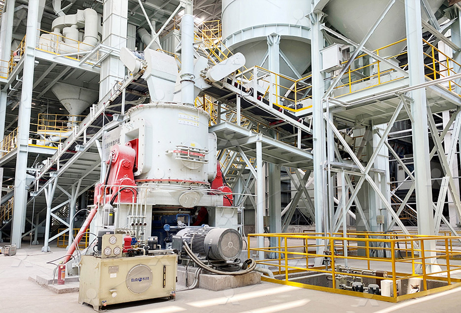
MTW European Type Trapezium Mill
Input size:30-50mm
Capacity: 3-50t/h
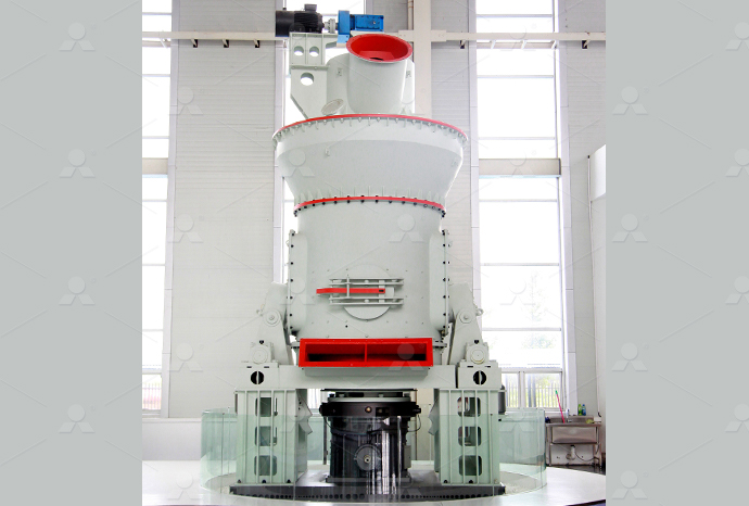
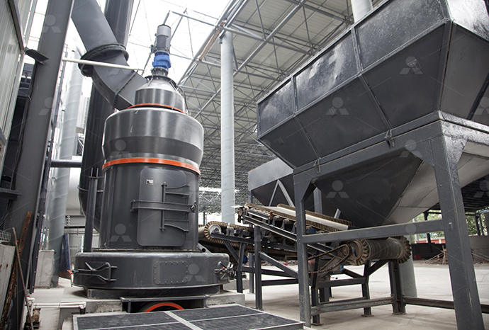
LM Vertical Roller Mill
Input size:38-65mm
Capacity: 13-70t/h
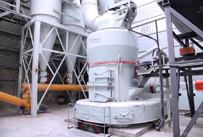
Raymond Mill
Input size:20-30mm
Capacity: 0.8-9.5t/h
Sand powder vertical mill
Input size:30-55mm
Capacity: 30-900t/h
LUM series superfine vertical roller grinding mill
Input size:10-20mm
Capacity: 5-18t/h
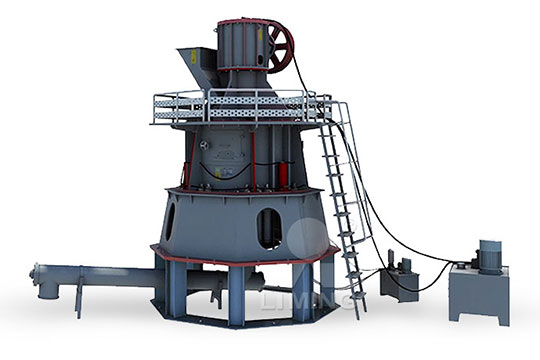
MW Micro Powder Mill
Input size:≤20mm
Capacity: 0.5-12t/h

LM Vertical Slag Mill
Input size:38-65mm
Capacity: 7-100t/h
LM Vertical Coal Mill
Input size:≤50mm
Capacity: 5-100t/h
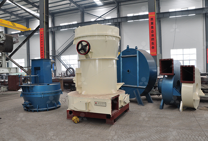
TGM Trapezium Mill
Input size:25-40mm
Capacity: 3-36t/h
MB5X Pendulum Roller Grinding Mill
Input size:25-55mm
Capacity: 4-100t/h
Straight-Through Centrifugal Mill
Input size:30-40mm
Capacity: 15-45t/h
Electromagnetic ultrafine ore powder processing equipment control schematic diagram
1 schematic representation of fabrication of ultrafine
In the present work, ultrafine powders of ptype (Bi, Sb)2Te3 alloys are fabricated through high energy ball milling using stearic acid as a process control agent (PCA)The present research's objective is to investigate the electromagnetic radial powder compaction process and its effect on the densification, microstructure and mechanical properties of the AlElectromagnetic powder compaction equivalent The paper presents a study on the effectiveness of the grinding process in an electromagnetic mill devoted to ultrafine grinding, and the influence of processing parameters on the mill’s Grinding and classification circuit diagram, where 1: This research studied the optimization of the jet mill grinding process of ultrafine metallurgical powders in a smallscale 4” jet mill The research was aimed to understand the effects of feed Process optimization of jet mills for metallurgical powder production
.jpg)
Electromagnetic Powder Compaction: An Experimental Study of
2024年3月31日 This study focuses on an innovative technique for powder compaction—electromagnetic powder compaction—and its effects on titanium (Ti) powder Figure 3 depicts the range of application and the level of size reduction of the principal grinding methods used in mineral ore processing, reducing the particle size from 500 mm to sub15 µm EnergyEfficient Advanced Ultrafine Grinding of ProQuestAbstract— The paper presents optimizing control of the electromagnetic grinding system The electromagnetic grinding is a complex process, thus formulation of the optimization problem is Power Optimizing Control of Grinding Process in Electromagnetic 2015年7月21日 This article discusses the range of application of ultrafine grinding for processing mineral raw materials and presents examples of the successful use of this technology in the Ultrafine Grinding in Contemporary Flow Diagrams for Mineral
Ultrafine Grinding Process SpringerLink
2023年7月20日 Ultrafine particles can be produced with chemical and physical methods Chemical method includes vapor phase method, liquid phase method, and reciprocal reaction The paper presents a study on the effectiveness of the grinding process in an electromagnetic mill devoted to ultrafine grinding, and the influence of processing parameters on the mill’s (PDF) Grinding Kinetics Adjustment of Copper Ore Grinding in an Download scientific diagram A schematic of the laser powder bed fusion (LPBF) process from publication: Partscale Thermal Simulation of Laser Powder Bed Fusion Using Graph Theory: Effect of A schematic of the laser powder bed fusion (LPBF) Download scientific diagram (a) Schematic of laser powder bed fusion (LPBF) process, (b) gasatomized (argon) 174 precipitationhardened (PH) stainless steel (SS) powder; (c) vertically and (d (a) Schematic of laser powder bed fusion (LPBF) process, (b

Schematic diagram of (a) SLM process and (b)
Download scientific diagram Schematic diagram of (a) SLM process and (b) powderflown DED process from publication: Materials and manufacturing renaissance: Additive manufacturing of high Download scientific diagram Basic diagram of Powder bed fusion equipment from publication: AN INSIGHT OF 3D PRINTING TECHNOLOGY IN PHARMACEUTICAL DEVELOPMENT AND APPLICATION : AN UPDATED REVIEW Basic diagram of Powder bed fusion equipmentDownload scientific diagram Schematic diagram of (a) the wire flame process and (b) the powder flame process; (c) schematic diagram of the wire arc process; (d) schematic diagram of APS Schematic diagram of (a) the wire flame process and (b) the powder Download scientific diagram Schematic diagram of the UAP3 magnetic mill: (1) electromagnetic inductors; (2) water cooling circuit; (3) tube furnace; (4) flow reactor made of stainless steel; (5 Schematic diagram of the UAP3 magnetic mill: (1) electromagnetic
Schematic flow sheet of hydrometallurgical route for ultrafine
Download scientific diagram Schematic flow sheet of hydrometallurgical route for ultrafine zinc production from industrial wastes from publication: Optimized Hydrometallurgical Route to Produce Download scientific diagram Electromagnetic powder compaction equivalent electric circuit diagram from publication: Experimental and numerical investigations on electromagnetic powder compaction Electromagnetic powder compaction equivalent electric circuit diagramDownload scientific diagram Schematic diagram of the iron ore pelletization process from publication: Influence of Pellet Basicity (CaO/SiO2) on Iron Ore Pellet Properties and Microstructure Schematic diagram of the iron ore pelletization processHowever, knowledge about relay logic and ladder diagrams is very useful Ladder Diagram Symbols Ladder diagrams differ from regular schematic diagrams of the sort common to electronics technicians primarily in the strict orientation of the wiring: vertical power “rails” and horizontal control “rungs”Relay Circuits and Ladder Diagrams Control

CNU Electromagnetic automatic feeding system in barite ore
The utility model discloses an automatic feed system of electromagnetism in processing of barite ore powder, vibration material selection mechanism is including the screening case, the feed inlet at screening roof portion is located first discharge gate on the first processingequipment under, the inside slope of screening case is provided with the vibration board, be connected with first Because of its flexibility and economies in the manufacture of AlMMCs, the liquid casting approach is a very fascinating technology Because of their high strength and increased wear resistance Schematic Diagram of Powder Metallurgy Technique (GoogleElectromagnetic forming is a forming method that employs the electromagnetic force to accomplish deformation of metal workpiece and is greatly suitable for high conductivity metalsThe schematic diagram of the electromagnetic formingSchematic diagram of the Direct Energy Deposition process The powder particles flow through the nozzle (blue) and it is melted by the focused laser (red) as it is being deposited to create a part Schematic diagram of the Direct Energy Deposition process The powder
Schematic diagram of the laboratory vertical stirred mill
Download scientific diagram Schematic diagram of the laboratory vertical stirred mill from publication: Optimization of stirred mill parameters for fine grinding of PGE bearing chromite ore Download scientific diagram Schematic of the laser powder bed fusion process from publication: Advances in Laser Additive Manufacturing of Cobalt Chromium Alloy MultiLayer Mesoscopic Schematic of the laser powder bed fusion processDownload scientific diagram Schematic diagram for the preparation process of powder metallurgy (PM) TiAl alloy HIP: hot isostatic pressing from publication: Microstructure and Mechanical Schematic diagram for the preparation process of powder 2023年9月13日 When the feed contains a large amount of qualified ultrafine powder, using this process can reduce the load on the crusher, reduce energy consumption per unit of ultrafine powder product, and improve operating efficiency Closed circuit process with pregrading7 basic process flows of ultrafine grinding ALPA Powder Equipment
Schematic Diagram A Complete Tutorial with Free Examples
The idea of schematic diagrams came into existence somewhere in 1300 AD when the firstever geographical map, which is now known as Atlas, was drawn Later, the same concept was used to draw the maps of stars and constellations As time passed, the structure of the schematic diagrams modified, and somewhere in the 20th century, leaving behind the traditional 2004年7月1日 Electromagnetic sheet metal forming (EMF) is a forming process driven by the dynamics of electromagneticmechanical phenomena In this highspeed process does not exist mechanical contact between Electromagnetic forming and powder processing: Trends and developments Download scientific diagram Schematic of the working principle of the powder atomization process from publication: Manufacturing Methods, Microstructural and Mechanical Properties Evolutions of Schematic of the working principle of the powder Download scientific diagram Schematic of a laser powder bed fusion process [20] from publication: Utilization of Additive Manufacturing in the Thermal Design of Electrical Machines: A Review Schematic of a laser powder bed fusion process [20]
Schematic diagram of electromagnetic sheet
Electromagnetic forming is an highspeed forming technique by application of Lorentz force on to the highly conducting sheet material in the absence of working medium and contact conditions [40,72 Download scientific diagram Schematic diagram of the powdercoating line setup The photograph depicted in Figure 2 shows a general overview of the developed powder coating equipment from Schematic diagram of the powdercoating line setup The Download scientific diagram The schematic diagram of pulsed electromagnetic blank holder for electromagnetic forming from publication: Design, Implementation, and Testing of a Pulsed The schematic diagram of pulsed electromagnetic blank holder 2004年10月12日 A comprehensive review and assessment of the electromagnetic forming process is presented Even though electromagnetic forming is a technology known for a few decades, renewed interest in it for industrial applications is currently taking place Emphasis is mainly placed on the physical phenomena that govern the process as well as its main Electromagnetic forming and powder processing: Trends and
.jpg)
Schematic View of Electromagnetic Stir Casting SetUp
Download scientific diagram Schematic View of Electromagnetic Stir Casting SetUp from publication: Electromagnetic Stir Casting and its Process Parameters for the Fabrication and Refined the Laser powder bed fusion (LPBF) is one class of metal additive manufacturing (AM) used to fabricate highquality complexshape components This technology has significantly progressed over the last Schematic representation of the powder bed fusion processDownload scientific diagram Schematic process flow for treating chalcopyrite, from raw ore to copper wire rod Each vertical black line is a process step with the material inputs represented by Schematic process flow for treating chalcopyrite, from raw ore to Download scientific diagram Schematic diagram of the powdercoating line setup from publication: PRODUCTION OF NEW THERMOPLASTIC MATRIX COMPOSITES FOR HIGH DEMANDING APPLICATIONS PRIMOSPIRE Schematic diagram of the powdercoating line setup
A schematic of the laser powder bed fusion (LPBF)
Download scientific diagram A schematic of the laser powder bed fusion (LPBF) process from publication: Partscale Thermal Simulation of Laser Powder Bed Fusion Using Graph Theory: Effect of Download scientific diagram (a) Schematic of laser powder bed fusion (LPBF) process, (b) gasatomized (argon) 174 precipitationhardened (PH) stainless steel (SS) powder; (c) vertically and (d (a) Schematic of laser powder bed fusion (LPBF) process, (b Download scientific diagram Schematic diagram of (a) SLM process and (b) powderflown DED process from publication: Materials and manufacturing renaissance: Additive manufacturing of high Schematic diagram of (a) SLM process and (b) Download scientific diagram Basic diagram of Powder bed fusion equipment from publication: AN INSIGHT OF 3D PRINTING TECHNOLOGY IN PHARMACEUTICAL DEVELOPMENT AND APPLICATION : AN UPDATED REVIEW Basic diagram of Powder bed fusion equipment
Schematic diagram of (a) the wire flame process and (b) the powder
Download scientific diagram Schematic diagram of (a) the wire flame process and (b) the powder flame process; (c) schematic diagram of the wire arc process; (d) schematic diagram of APS Download scientific diagram Schematic diagram of the UAP3 magnetic mill: (1) electromagnetic inductors; (2) water cooling circuit; (3) tube furnace; (4) flow reactor made of stainless steel; (5 Schematic diagram of the UAP3 magnetic mill: (1) electromagnetic Download scientific diagram Schematic flow sheet of hydrometallurgical route for ultrafine zinc production from industrial wastes from publication: Optimized Hydrometallurgical Route to Produce Schematic flow sheet of hydrometallurgical route for ultrafine Download scientific diagram Electromagnetic powder compaction equivalent electric circuit diagram from publication: Experimental and numerical investigations on electromagnetic powder compaction Electromagnetic powder compaction equivalent electric circuit diagram
.jpg)
Schematic diagram of the iron ore pelletization process
Download scientific diagram Schematic diagram of the iron ore pelletization process from publication: Influence of Pellet Basicity (CaO/SiO2) on Iron Ore Pellet Properties and Microstructure However, knowledge about relay logic and ladder diagrams is very useful Ladder Diagram Symbols Ladder diagrams differ from regular schematic diagrams of the sort common to electronics technicians primarily in the strict orientation of the wiring: vertical power “rails” and horizontal control “rungs”Relay Circuits and Ladder Diagrams Control